- 您现在的位置:买卖IC网 > Sheet目录2000 > ISD5008EYI (Nuvoton Technology Corporation of America)IC VOICE REC/PLAY 4-8MIN 28-TSOP
ISD5008
Publication Release Date: Oct 31 2008
- 30 -
Revision 1.2
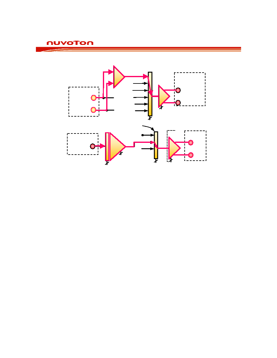
(CFG0) and they should all be ZERO to select the FTHRU path.
.
Power up the ANA OUT amplifier—
Bit AOPD controls the power up state of ANA OUT.
hat
ld be set to the
To select this mode, the following control bits must be configured in the ISD5008 configuration
registers. To set up the transmit path:
1.
Select the FTHRU path through the ANA OUT MUX—
Bits AOS0, AOS1 and AOS2 control
the state of the ANAOUT MUX. These are the D6, D7 and D8 bits respectively of
Configura tion Register 0
2
This is bit D5 of CFG0 and it should be a ZERO to power up the amplifier.
To set up the receive path:
1. Set up the ANA IN amplifier for the correct gain—Bits AIG0 and AIG1 control the gain settings
of this amplifier. These are bits D14 and D15 respectively of CFG0. The input level at this pin
determines the setting of this gain stage. Table 4 will help determine this setting. In this
example we will assume that the peak signal never goes above 1 volt p-p single ended. T
would enable us to use the 9dB attenuation setting, or where D14 is ONE and D15 is ZERO.
2. Power up the ANA IN amplifier—Bit AIPD controls the power up state of ANA IN. This is bit
D13 of CFG0 and should be a ZERO to power up the amplifier.
3. Select the ANA IN path through the OUTPUT MUX—Bits OPS0 and OPS1 control the state of
the OUTPUT MUX. These are bits D3 and D4 respectively of CFG0 and they should be set to
the state where D3 is ONE and D4 is ZERO to select the ANA IN path.
4. Power up the Speaker Amplifier—Bits OPA0 and OPA1 control the state of the Speaker and
AUX amplifiers. These are bits D1 and D2 respectively of CFG0. They shou
state where D1 is ONE and D2 is ZERO. This powers up the Speaker Amplifier and
MIC–
MIC+
6dB
Microphone
ANA OUT+
INP
VOL
ANA OUT–
SUM1
FTHRU
SUM2
Chip
Set
ANAOUT
MUX
3
1
AOS0
(AOPD)
AOS1
AOS2
( )
FILT0
ANA IN
Chip Set
.625
/
.883
/
1.
25
/
1
.767
AIG0
AIG1
( )
2
1(AIPD)
AMP
ANA IN
SP+
VOL
SP–
SUM 2
Speaker
2 OPA1
( )
OPA0
ANA IN
FILTO
2 OPS0
OPS1
( )
OUTPUT
MUX
MIC–
MIC+
6dB
Microphone
ANA OUT+
INP
VOL
ANA OUT–
SUM1
FTHRU
SUM2
Chip
Set
ANAOUT
MUX
3
1
AOS0
(AOPD)
AOS1
AOS2
( )
FILT0
MIC–
MIC+
6dB
Microphone
ANA OUT+
INP
VOL
ANA OUT–
SUM1
FTHRU
SUM2
Chip
Set
ANAOUT
MUX
FILT0
1
AOS0
(AOPD)
AOS1
AOS2
( )
AOS1
AOS2
( )
3
ANA IN
Chip Set
.625
/
.883
/
1.25
/
1
.767
AIG0
AIG1
( )
2
1(AIPD)
AMP
ANA IN
SP+
VOL
SP–
SUM 2
Speaker
2 OPA1
( )
OPA0
ANA IN
FILTO
2 OPS0
OPS1
( )
ANA IN
Chip Set
.625
/
.883
/
1.25
/
1
.767
AIG0
AIG1
( )
2
1(AIPD)
AMP
ANA IN
SP+
VOL
SP–
SUM 2
Speaker
2 OPA1
( )
OPA0
ANA IN
FILTO
2 OPS0
OPS1
( )
OUTPUT
MUX
发布紧急采购,3分钟左右您将得到回复。
相关PDF资料
ISL12008IB8Z
IC RTC I2C LO-POWER 8-SOIC
ISL12020MIRZ-T7A
IC RTC/CALENDAR TEMP SNSR 20DFN
ISL12022IBZ-T7A
IC RTC/CALENDAR TEMP SNSR 8SOIC
ISL12022MAIBZ
IC RTC/CALENDAR TEMP SNSR 20SOIC
ISL12022MIBZ-T7A
IC RTC/CALENDAR TEMP SNSR 20SOIC
ISL12022MIBZR5421
IC RTC/CALENDAR TEMP SNSR 20SOIC
ISL12023IVZ
IC RTC/CLDR TEMP SNSR 14-TSSOP
ISL12024IRTCZ
IC RTC/CALENDER 64BIT 8-TDFN
相关代理商/技术参数
ISD5008P
功能描述:IC VOICE REC/PLAY 4-8MIN 28-DIP RoHS:否 类别:集成电路 (IC) >> 接口 - 语音录制和重放 系列:ISD5008 标准包装:14 系列:- 接口:串行 滤波器通频带:1.7kHz 持续时间:8 ~ 32 秒 安装类型:通孔 封装/外壳:28-DIP(0.300",7.62mm) 供应商设备封装:28-PDIP 其它名称:90-21300+000
ISD5008PY
功能描述:IC VOICE REC/PLAY 4-8MIN 28-DIP RoHS:是 类别:集成电路 (IC) >> 接口 - 语音录制和重放 系列:ISD5008 标准包装:14 系列:- 接口:串行 滤波器通频带:1.7kHz 持续时间:8 ~ 32 秒 安装类型:通孔 封装/外壳:28-DIP(0.300",7.62mm) 供应商设备封装:28-PDIP 其它名称:90-21300+000
ISD5008S
功能描述:IC VOICE REC/PLAY 4-8MIN 28-SOIC RoHS:否 类别:集成电路 (IC) >> 接口 - 语音录制和重放 系列:ISD5008 标准包装:14 系列:- 接口:串行 滤波器通频带:1.7kHz 持续时间:8 ~ 32 秒 安装类型:通孔 封装/外壳:28-DIP(0.300",7.62mm) 供应商设备封装:28-PDIP 其它名称:90-21300+000
ISD5008SD
制造商:未知厂家 制造商全称:未知厂家 功能描述:SINGLE CHIP VOICE RECORD PLAYBACK DEVICE 4-, 5-, 6-, AND 8- MINUTE DURATIONS
ISD5008SERIES
制造商:未知厂家 制造商全称:未知厂家 功能描述:Single-Chip Voice Record/Playback Device
ISD5008SI
功能描述:IC VOICE REC/PL 4-8MIN IN 28SOIC RoHS:否 类别:集成电路 (IC) >> 接口 - 语音录制和重放 系列:ISD5008 标准包装:14 系列:- 接口:串行 滤波器通频带:1.7kHz 持续时间:8 ~ 32 秒 安装类型:通孔 封装/外壳:28-DIP(0.300",7.62mm) 供应商设备封装:28-PDIP 其它名称:90-21300+000
ISD5008SIR
功能描述:IC VOICE REC/PL 4-8MIN IN 28SOIC RoHS:否 类别:集成电路 (IC) >> 接口 - 语音录制和重放 系列:ISD5008 标准包装:14 系列:- 接口:串行 滤波器通频带:1.7kHz 持续时间:8 ~ 32 秒 安装类型:通孔 封装/外壳:28-DIP(0.300",7.62mm) 供应商设备封装:28-PDIP 其它名称:90-21300+000
ISD5008SY
功能描述:IC VOICE REC/PLAY 4-8MIN 28-SOIC RoHS:是 类别:集成电路 (IC) >> 接口 - 语音录制和重放 系列:ISD5008 标准包装:14 系列:- 接口:串行 滤波器通频带:1.7kHz 持续时间:8 ~ 32 秒 安装类型:通孔 封装/外壳:28-DIP(0.300",7.62mm) 供应商设备封装:28-PDIP 其它名称:90-21300+000